Stamps! Make fabulous stamps out of designs you drew by hand on paper, without spending a year in Adobe Illustrator! Then use your stamp to stamp things! Huzzah!
- Safety
- 🚨 SAFETY WARNING 🚨
- Tools and Materials
- Step One: Draw Something
- Step Two: Photograph your Drawing
- Step Three: Image Editing
- Photoshop
- GIMP
- Step Four: Toolpathing
- Mods
- Machining Operation One: Roughing
- Machining Operation Two: Finishing
- Step Five: Machining
- Setup
- Machining Time!

If you are new to desktop CNC milling, take your time and get comfortable with both the machine control software (Carbide Motion) and the toolpathing program (Mods). Once you get the hang of it, you will be able to churn out many stamps per hour, particularly if you work as a team and have access to a few machines.
Safety
[borrowed from the Nomad 3 Milling Machine Tutorial]
🚨 SAFETY WARNING 🚨
- This machine utilizes a very sharp tool that spins at high speeds. Unless you are switching out the end mill, KEEP YOUR FINGERS CLEAR OF THE SPINDLE.
- When the Nomad 3 is running, KEEP THE SAFETY COVER CLOSED NO MATTER WHAT. If you need to open it for any reason, pause the machine in your program and let it come to a stop before opening the cover.
- Make sure the Nomad 3 is always within ear/eyeshot. Do not leave the Nomad 3 unattended while it is running, as you need to be able to shut it down in the event that something breaks, dislodges, or generally goes wrong.
- Be very careful when removing stock. Make sure your hands are clear and out of the way of any sharp tools.
- If the end mill breaks, stop the machine and abort the project. Make sure the spindle is no longer moving before opening the cover and switching out the end mill.
- Make sure stock is secured firmly to the waste board. If it's not secured, it can dislodge and go flying during the milling process, potentially damaging the Nomad 3 and/or injuring yourself and others.
- Clear and vacuum the Nomad 3 after each use. Do not vacuum it while it's running.
- Parts of this tutorial require the use of a saw to divide linoleum slabs into smaller blocks. Safe use of this tool is outside the scope of this tutorial; ask for help if unfamiliar!
Tools and Materials
[TODO: insert image of tools and materials]
You will need:
- a Carbide Nomad 3 desktop CNC mill, or a suitable alternative (>10k RPM spindle, > 50 mm/side working area, 1/8” collet)
- a 1/32” flat end mill
- a 1/8” flat end mill
- double-sided tape, such as Scotch Permanent (which isn’t really permanent, but that is good thing in this case)
- note: you do not need tape if your mill has a vise
- a camera, like the one on your phone
- a computer with an image editing program, like Photoshop or GIMP
- a slab of linoleum block for printing, like the brown Speedball type
- a saw for blocks; a large sliding chop saw is ideal
- a vacuum cleaner
- stamping supplies: an ink pad, or a brayer, a bench hook, and some ink
- a stamping substrate you wish to mark, like paper
Step One: Draw Something
Find a black marker and a sheet of white paper and draw your stamp design! The only constraint here is minimum feature size, meaning the smallest line thickness or smallest white space you can resolve. This is dependent on how much your drawing needs to shrink down to make a stamp. Here is a rough guide:
Drawing Size | Stamp Size | Drawing:Stamp Ratio | Minimum Drawing Feature Size (lines, which get inked) | Minimum Drawing Feature Size (white spaces, which turn into gaps) |
4” x 6” (~100 mm x ~150 mm) | 2” x 3” (~50 mm x ~75 mm) | 2:1 | 3 mm (~1/8”) | 2 mm (~5/64”) |
2” x 2” (~50 mm x ~50 mm) | 2” x 2” (~50 mm x ~50 mm) | 1:1 | 1.5 mm (~1/16”) | 1 mm (1/25.4”) |
We are using a 1/32” (~0.8 mm) mill for finishing passes, so technically the smallest minimum gap in the machined stamp can be 1/32” (~0.8 mm), but leaving a bit more clearance is helpful. The black lines in the drawing will eventually become “proud” areas of the stamp which stick out and pick up ink, seen here:

Lines need to be a bit thicker so they aren’t so delicate they break during normal stamp use. Bella’s example from the December Sip ‘n Create is ideal, and ended up getting reduced by a factor of ~1.5:1:

Linoleum is cheap, and if you drop below the rules the stamp will probably still look great! You just run a greater risk of stamp damage during use, but damaged stamps still look nice. If you are just getting started, a simple way to scale well is to use a normal-sized marker (think standard Sharpie) and draw at the same scale as your eventual stamp.
Step Two: Photograph your Drawing
Place the drawing flat on a table with reasonably bright light around, and photograph it head-on using your camera. A phone is great for this; we aren’t making high resolution stamps so the images don’t need to be excellent. Just try to avoid shadows and it will be fine; the image of Bella’ stamp above is perfect, for example.
Step Three: Image Editing
Send your image to your computer, via cloud drive, cable, Slack, email, or other means. Open it in a reasonably sophisticated raster image editor like Photoshop or GIMP.
Photoshop

Copy the image from the background into a new layer and delete the background layer:

Rotate the image as needed, and then crop to the image boundaries. Here, we want the four arms of the design to be vertical and horizontal. Adding a guide helped with the rotation:

Erase parts you don’t want included in the stamp. Here, that means the bits of table that remained in the photo, along with Bella’s signature, only deleted because its feature size is too small:

Use the Threshold function to turn the image black-and-white, adjusting the slider until you are satisfied with the resulting stamp preview. When you have to choose between white splotches on black lines and black noise on the white background, go for the former as the toolpathing routine will ignore the tiny defects:

If you still have a bit of noise on the background, zoom in and erase it, seen in progress here:

Rescale your image so that it is 300 DPI and the long dimension matches your desired stamp large dimension, minus 0.1”. For example, we want this stamp to end up no larger than 3” on its longer side, so I scale the longest edge to (3” - 0.1”) * (300 DPI) = 870 pixels:

Now, resize the canvas so it is 0.1” longer on each side, with the art centered. So the longest side in our case returns to 3”. This works out to an increase of 30 pixels in each direction, so include a +15 offset in each dimension to keep the art centered:

This adds a bit of machined buffer on all sides of the design, ensuring the stamp won’t have an annoying bit of unwanted material hanging down on one edge. It also makes machine alignment less critical.
Now, add a layer filled with white below the art layer to fill in the transparent erase marks:

Export the image as a *.png and move on to toolpathing!
GIMP

Crop and rotate the image to the precise boundaries of the design, leaving as little space on each side as possible. Here, we oriented the four arms of the design to the X/Y axes:

Erase parts you don’t want included in the stamp. Here, that means the bits of table that remained in the photo, along with Bella’s signature, only deleted because its feature size is too small:

Use the Threshold function to turn the image black-and-white, adjusting the slider until you are satisfied with the resulting stamp preview. When you have to choose between white splotches on black lines and black noise on the white background, go for the former as the toolpathing routine will ignore the tiny defects:

If you still have a bit of noise on the background, zoom in and erase it, seen in progress here:

after a minute or so of de-noising:

Rescale your image so that it is 300 DPI and the long dimension matches your desired stamp large dimension, minus 0.1”. For example, we want this stamp to end up no larger than 3” on its longer side, so I scale the longest edge to (3” - 0.1”) * (300 DPI) = 870 pixels:

Now, resize the canvas so it is 0.1” longer on each side, with the art centered. So the longest side in our case returns to 3”. This works out to an increase of 30 pixels in each direction, so include a +15 offset in each dimension to keep the art centered:


This adds a bit of machined buffer on all sides of the design, ensuring the stamp won’t have an annoying bit of unwanted material hanging down on one edge. It also makes machine alignment less critical.
Now, add a layer filled with white below the art layer to fill in the transparent erase marks:

Export the image as a *.png and move on to toolpathing!
Step Four: Toolpathing
Mods
We shall use Mods! Head over to Mods Community Edition, where you shall find a mostly blank window:

If you click once, you’ll see more navigation instructions:

Remember what I call the First Rule of Mods: if you ever get lost or make a mistake, just refresh the browser window to start over.
Right-click in the white area to bring up the context menu:

Left click ‘programs’ for the next menu:

Select ‘open program’ (not ‘open program from file’):

Select Machines → Carbide Nomad → PCB, scrolling with your mouse wheel if needed. This will bring up the complete toolpathing program, built out of modules. If your browser window is fairly small (as mine is, for screenshotting), the program will be tiny as it zooms to fit the window:

It looks complicated! But most of the modules, which are connected with cyan lines, are intermediate processing steps that we don’t need to fuss with. The only modules that matter to us are ‘read png’, ‘mill raster 2d’, and ‘path to Carbide Nomad G-code’, highlighted here:

Use the scroll wheel to zoom in to the ‘read png’ module in the lower left corner:

Click ‘select png file’, locate the file you recently exported, and click ‘open’. The image should arrive in the ‘read png’ module window, and the scaling should look correct (3.000” x 2.820”, in this case):

Mods machines away the black areas on the image, but we want to keep the lines! So hit ‘invert’. Note that you could have done this previously in your image editor. Up to you.

Now we can make the actual machining paths! This is probably a good time to mention that we’re going to machine the stamp twice, which led to the requirement for both a 1/32” and a 1/8” flat end mill.
Machining Operation One: Roughing
In the first operation, we will mill away as much bulk material as possible using a large 1/8” flat end mill. This work won’t fill in all the details of the design, but it will dramatically speed up the machining process, depending on the complexity of the design.
Head over to the ‘path to Carbide Nomad G-code’ module and enter the following values:
cut speed: 10 mm/s
plunge speed: 5 mm/s
jog height: 3 mm
spindle sacrpeed: 10000 RPM
The remaining options, like tool number and format, can be left as their defaults:

Now, zoom out and pan over to the ‘mill raster 2d’ module and enter the following values:
tool diameter: 3.175 mm / 0.125”
cut depth: 0.51 mm / 0.02”
max depth: 0.51 mm / 0.02”
offset number: 0
The remaining options, like offset stepover and path merge, can be left as their defaults:

Press ‘calculate’ to download the *.nc file and preview the toolpath, which will appear in a new tab. If you have popups turned off, allow them for the site and click ‘view’:

Go find the *.nc file that just downloaded and rename it to ‘[filename]_roughing.nc’ so it’s clear which tool you should use. That’s it for the roughing pass! Time for finishing!
Machining Operation Two: Finishing
In the second operation, we will mill the remaining sections that the 1/8” mill missed using the 1/32” mill. We’d like to avoid re-machining parts the larger tool removed, so we’ll reduce the offset number of this step to 1 to mimic rest machining, the term for skipping prior machining steps. Adjusting the offset isn’t perfectly efficient, since the smaller mill will still run around the entire perimeter of the design (even where it isn’t needed), but the total machining time is still dramatically reduced by avoiding the bulk of material removal. You can verify this later if you like, by using Carbide Motion to check the total machining time for a 1/32” mill with the offset set to 0. First, head over to the ‘path to Carbide Nomad G-code’ module and enter the following values:
cut speed: 10 mm/s
plunge speed: 5 mm/s
jog height: 3 mm
spindle speed: 10000 RPM
The remaining options, like tool number and format, can be left as their defaults:

Now, zoom out and pan over to the ‘mill raster 2d’ module and enter the following values:
tool diameter: 0.7937 mm / 0.03125”
cut depth: 0.51 mm / 0.02”
max depth: 0.51 mm / 0.02”
offset number: 3
The remaining options, like offset stepover and path merge, can be left as their defaults:

Press ‘calculate’ to download the *.nc file and preview the toolpath, which will appear in a new tab. If you have popups turned off, allow them for the site and click ‘view’:

Go find the *.nc file that just downloaded and rename it to ‘[filename]_finishing.nc’ so it’s clear which tool you should use.
Before you move on to machining, take a close look at the toolpathing previews! Do they make sense? Did you properly invert the source image so the right side is machined away? Did you mirror text so it shows up correctly on stamped paper? Remember, the milling machine will only remove material directly beneath the indicated lines in the preview. In the finishing path shown above, for example, most of the little circle cutouts at the ends of the “needles” in the design don’t get carved out, since the 1/32” mill is too large. We decided this was fine for the finished stamp, but one could avoid this by changing the initial design (either with marker or Photoshop), or by enlarging the stamp a bit. There are smaller mills available but they are extremely delicate, so we recommend basing your designs around what a 1/32” mill can successfully machine.
Step Five: Machining
First, prepare your stock. Cut a piece of linoleum down to the same dimensions as your finished file. For this example, that means 3” x 2.82”, or 76.2 mm x 71.6 mm. It doesn’t have to be perfect, but try to err on the side of “smaller”; think 3.00” +0.00” / -0.05”. Use caution during the sawing process; as mentioned earlier, this is not a saw tutorial so be sure ask for help if you are unfamiliar.
Setup

Download and install Carbide Motion, the program used to control the Nomad 3. Connect the machine to your computer using a USB cable, and connect the zeroing probe and power brick as well. Turn on the mill by pressing the large silver button on the lower right. The lights should turn on:

Open Carbide Motion and press Connect to Machine. If this is your first time using the software, you will need to follow the wizard instructions to add a Nomad 3:

Once you successfully connect to the Nomad, press Initialize Machine:

The Nomad will start moving about, homing its three axes. After doing this, the spindle will move to the center and ask you to insert a tool:

Locate a 1/8” flat end mill; the package will be marked, but pull the mill out and make sure it looks like the right tool; the cutting end should be the same diameter as the shank:

Open the safety shield on the front of the mill by lifting up on the aluminum handle. Carefully remove the mill from its holder (the business end is sharp!) and insert the mill into the collet such that around 3/4” (~20 mm) sticks out, and hand tighten the collet nut so it doesn’t slip out:

Locate the two collet wrenches and hold the larger one in your left hand. Slip the smaller wrench onto the flats on the spindle and the larger wrench onto the hexagonal black collet nut. Tighten the nut by pulling your hands towards each other until it is snug. Don’t over-tighten; it just needs to be a bit past hand-tight!
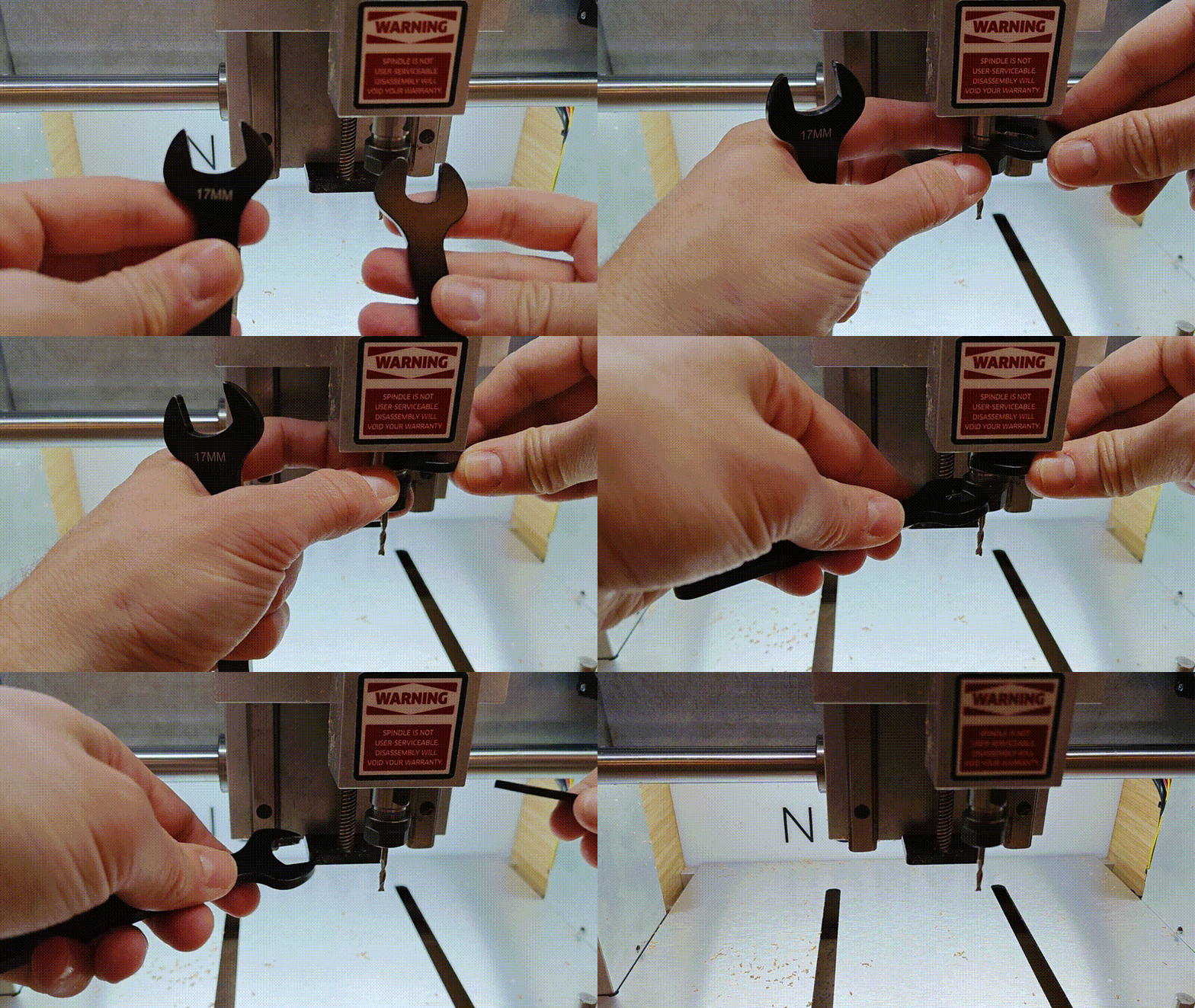
Close the safety shield and press Resume on the ‘Tool Change Required’ dialog. The machine will automagically measure the length of the mill using its built-in probe:

Add some double-sided tape to the underside of your linoleum block. If you’re using the recommended Scotch [semi-] Permanent double-sided stuff, one strip per inch of stock is more than enough:
When you install the material on the bed, you want it to be square to the X/Y axes. A simple way to do this is to use a few scrap blocks to align the stock to the machine bed and space it out from the edge, and then press the block down. Be sure to give the bed a quick wipe with your hand first to remove any pesky chips the vacuum may have missed last time:
Press the Jog button:

Carbide Motion will ask if you’d like to measure the tool; since you’ve just done, that, you can hit Continue:

The Jog dialog lets you manually move the spindle around using the arrow keys on your keyboard or the onscreen arrow buttons. Be careful doing this: the machine doesn’t know where the stock is, so it is quite possible to crash the mill into the linoleum block! Take it slow when you are starting out.
By default, each time you press an arrow key the spindle only moves a fraction of a millimeter. Once you are comfortable moving the spindle around slowly, you can increase the jog increment. If you bump it all the way up to ‘Fast’, the spindle will keep moving as long as the key is pressed down. Again, be careful not to crash into the work surface or stock!

Now, jog the spindle so that it is roughly over the center of the linoleum block, and around 3/4” (~20 mm) above the stock. Open the safety cover and install the safety override magnet below the sensor directly above the power button, which will allow you to run the probe routine with the cover open. Note! Overriding the safety interlock is inherently unsafe! We need to do this so that we can hold the Z-probe in the right place, but be extra careful (extra-extra careful) to avoid pinching your fingers.
Attach the Z-probe magnet to the shank of the end mill and position the probe plate directly under the spindle, above the linoleum block. Briefly (and gently) touch the probe plate to the mill and note the LED turning from green to red, indicating it detects the bit:

Press the Probe button:

Select the Z Probe option in the popup:

Use one hand to hold the zeroing plate directly under the mill, ensuring that it is resting flat on the two perpendicular black plastic ridges and not the plastic base with the screws. You’ll need to hold it steady so it doesn’t tilt over to a corner; the metal plate on top should be parallel with the top of the linoleum block:

Quadruple-check that the hand you are using to keep the leveling probe in place is not under the mill, and press the Begin Probe button:

The spindle will slowly drop down until the probe detects contact with the mill and turns red. Once this happens, the spindle will rise up again and the probe program will be finished. At this point, you can remove the safety override and close the shield.

Put the probe away back on top of the Nomad case, and store the magnet clip on one of the bolts. This is important to avoid accidentally triggering the probe during a job:

Now, use the X+, X-, Y+, and Y- buttons to jog the spindle until the center of the mill is roughly over the lower-left corner of the linoleum block. This doesn’t have to be perfect since we allowed for a bit of slop during file prep, but try to get it within a millimeter or so. You can drop the Increment down to 1 mm or lower to dial this in if needed. It may be useful to drop the Z axis a bit too and use the safety override to carefully line up the spindle with the door open.


Once both X and Y axes are lined up, press the Set Zero button:

Press the Zero X and Zero Y button, but not the Zero Z button. We already took care of that with the probe:

This will set the X and Y values to zero:

Great work! The stock is squared and secured; the first tool is installed; the machine is initialized; and the axes are all properly zeroed. Time to machine a stamp!
Machining Time!
Press the Run button, then the Load New File button:

Locate the roughing G-code file you created earlier, which should be named ‘[filename]_roughing.nc’ if you remembered to change it after downloading. The initial dialog should show dimensions that make sense: length and width are stamp-sized, and ‘Cutting depth below program zero’ is -0.51 mm. You will also see a time estimate which should be well under ten minutes unless your stamp is enormous. After reviewing these values, click Top View on the top menu bar:

This will bring up an overhead preview of the actual machining path, which should match the preview you saw earlier in mods. If it looks good, press Done.

Now, press Start Job, then Start:

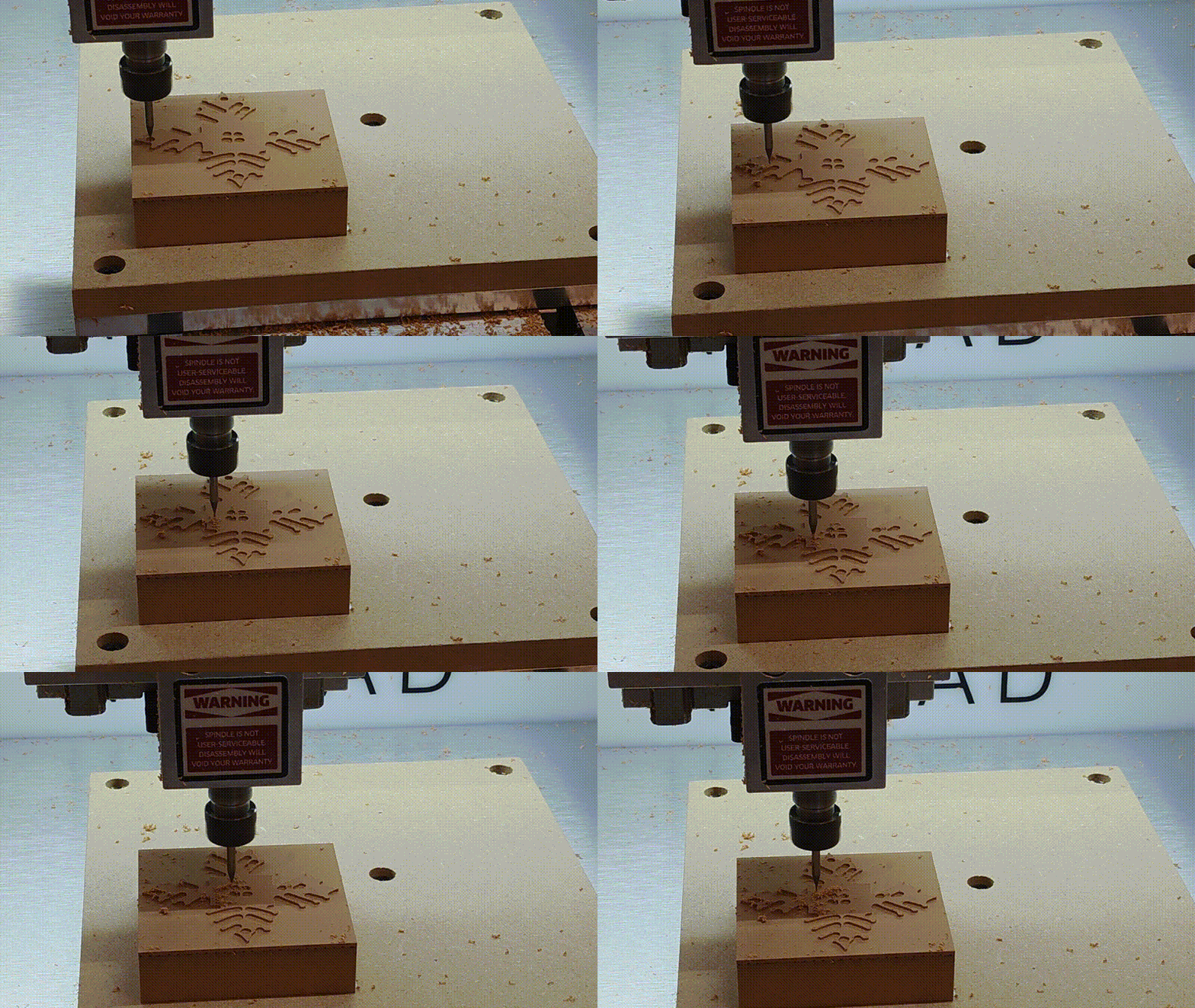
The roughing job will immediately commence! If anything looks fishy, you can press Pause, or just lift the front cover to stop the roughing pass. Generally speaking, “fishy” means the spindle motor stalling or severely bogging down, or the mill crashing into the workpiece or the table, or anything like that. If you’ve followed these instructions you shouldn’t have any issues, but if it’s your first time, make sure an instructor looks over your work before hitting ‘Start’.
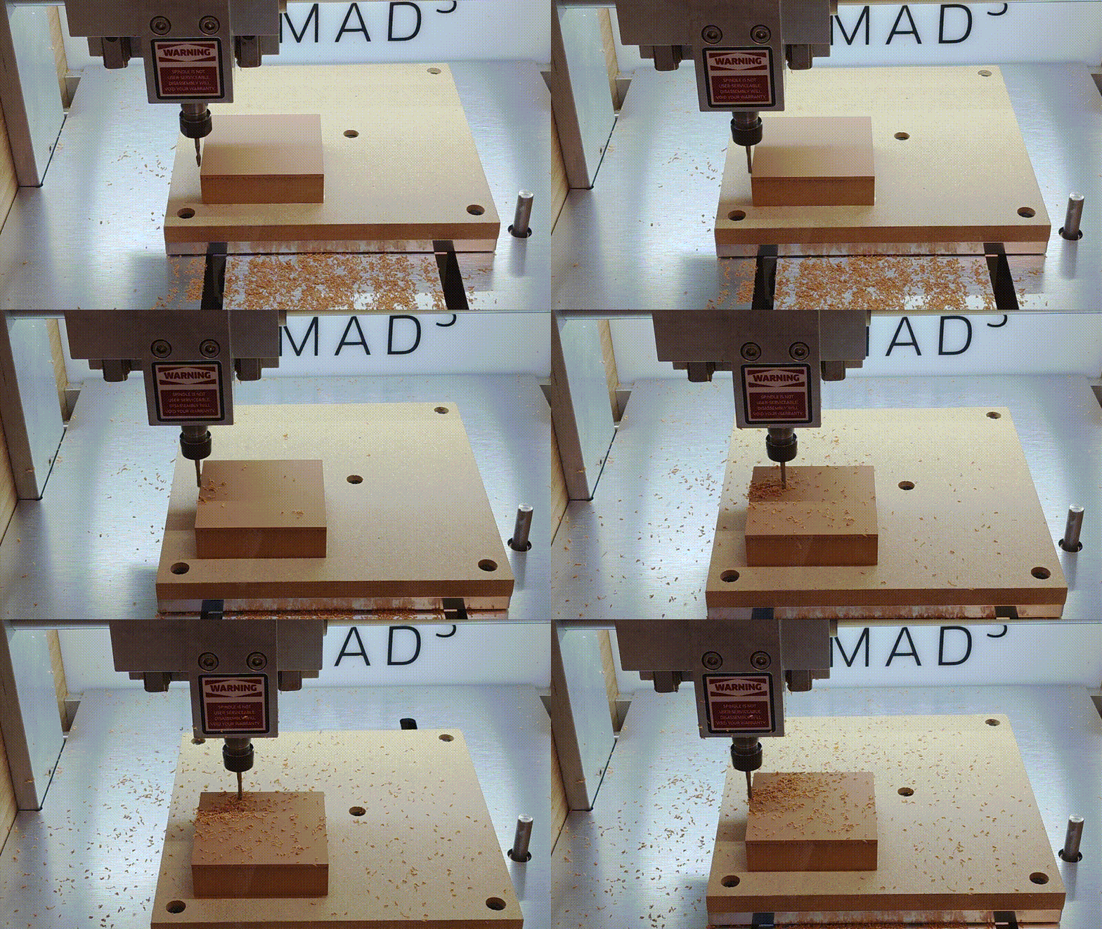
Monitor the job as it progresses. When the job finishes, the spindle will shut down and the table will advance all the way towards you. Once it stops, you can open up the front cover and gently vacuum away the debris:

Now, press Run to return to the main menu and press Load New Tool to change over to the 1/32” end mill for finishing:

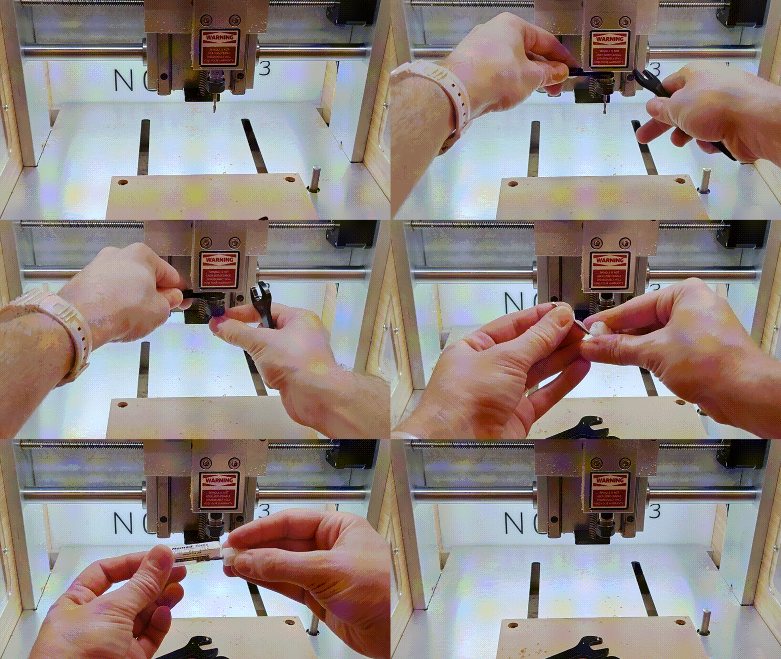
The spindle will wander over to the load tool position and the Nomad will prompt you to change the tool. Open the cover and loosen the collet by holding the larger wrench in your right hand and pulling your hands together. Please don’t put the mill down without first stowing it in the proper case:
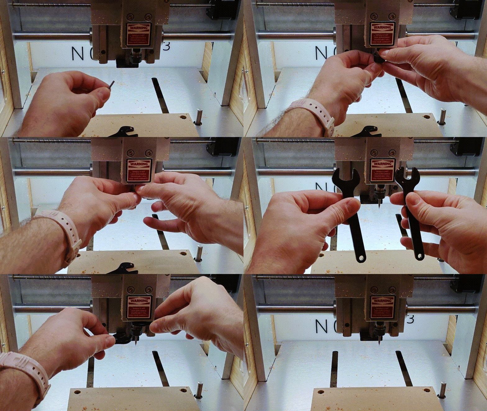
Now install the 1/32” flat end mill as you installed the larger one previously:
Close the lid and press Resume. The Nomad will measure the end mill:

Now hit Load New File and locate the finishing pass G-Code you created earlier, which should be named ‘[filename]_finishing.nc’. Preview the file as you did with the roughing pass and verify that everything looks sane:

Done —> Start Job —> Start:
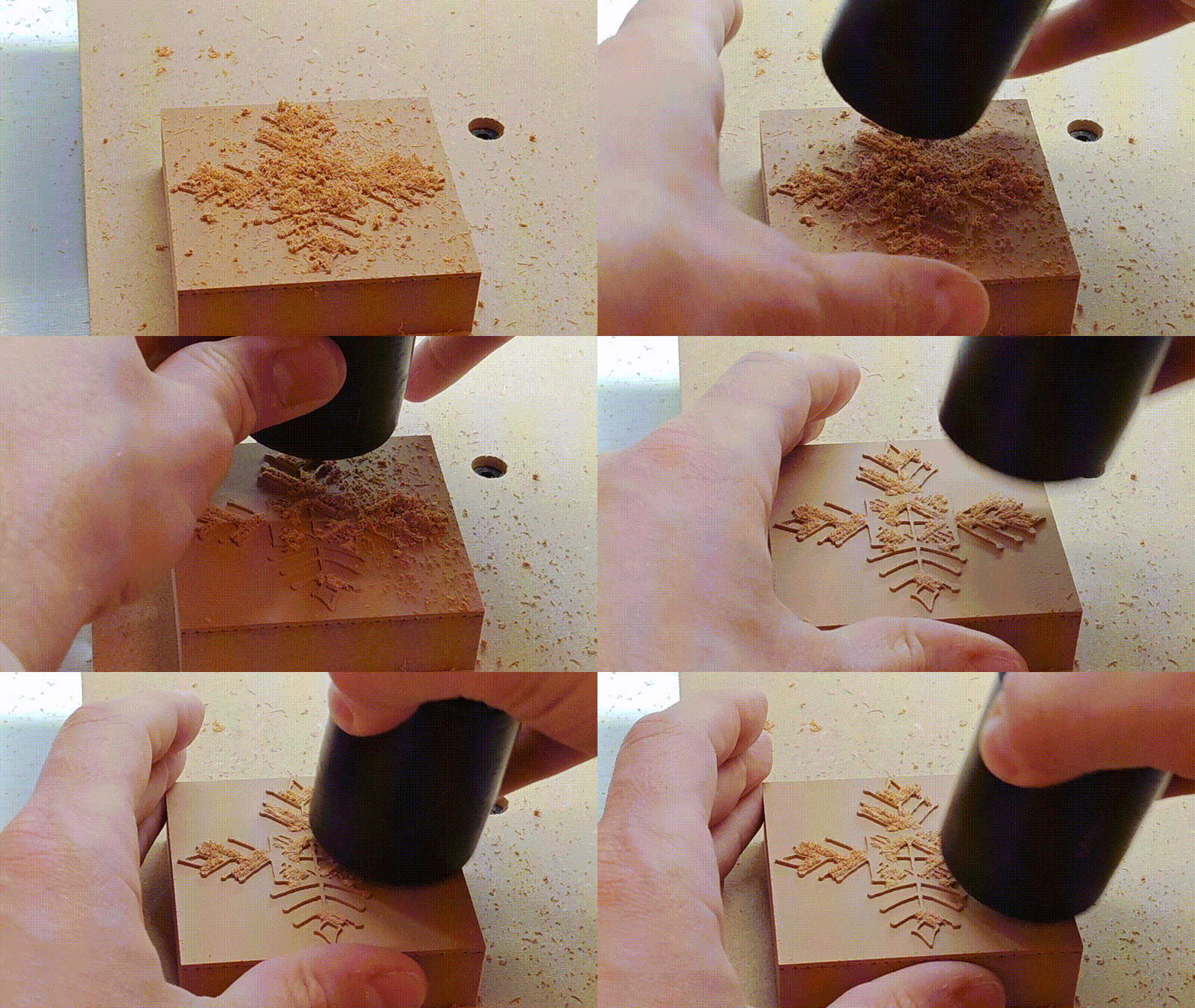
Vacuum:
Remove the mill before pulling off the stamp, since the latter requires some force; stowing mill in storage case not shown here but still important:

Now remove the stamp by pulling it directly towards you, being sure to brace your thumbs on the machine bed to avoid stressing the Y-axis. This can be difficult, so get help if you need it:

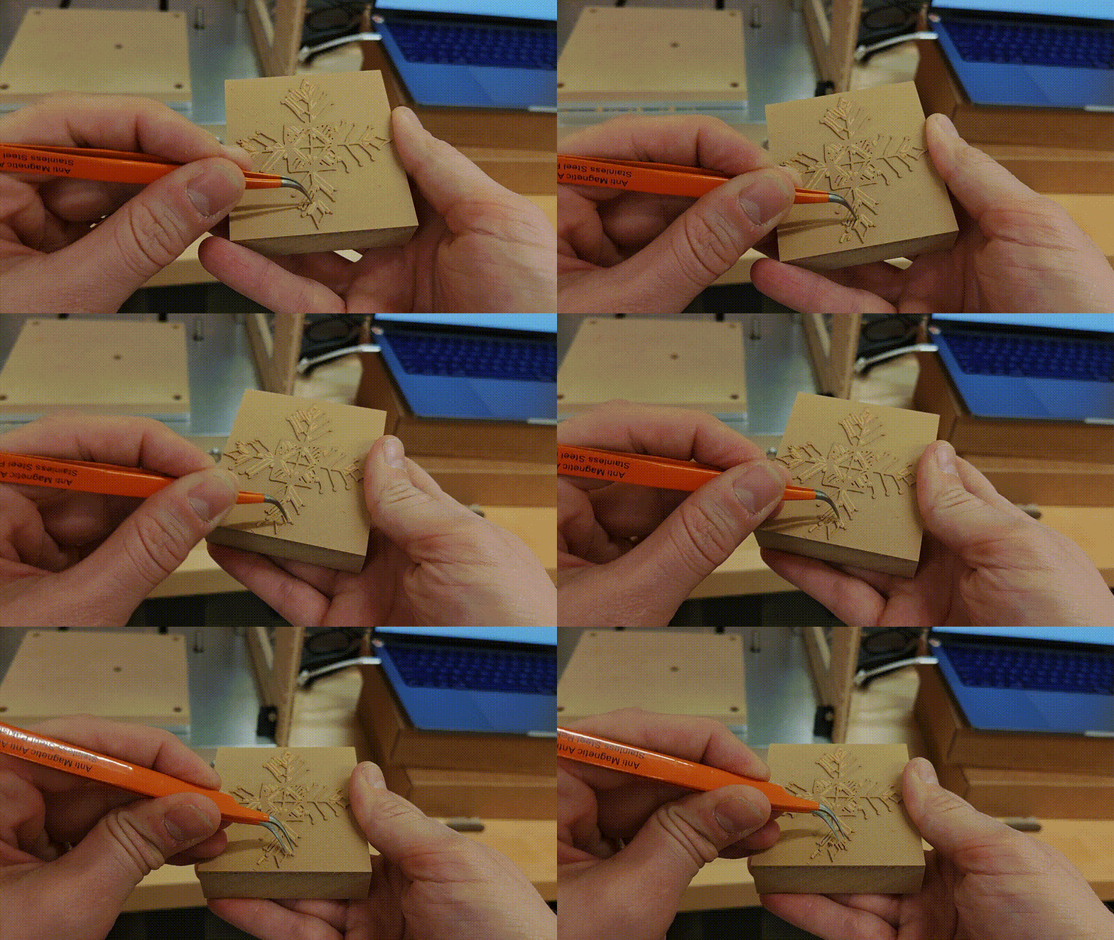
Depending on the detail level of your stamp, you may need to pick a few crumblies out of the gaps and re-vacuum to get it nice and clean. This is easy with a pair of sharp tweezers or a set of dentist tools. A soft nylon brush also works well:
Now give your stamp a try! Remember that linoleum block stamps aren’t quite as compliant as the rubber stamps you may be used to, so use plenty of ink and press down hard. It can be helpful to put a rubber sheet behind the paper, or to place the paper on an inked upside-down stamp and press down with a brayer. Don’t forget to wash your stamp when you’re done, and try not to cross-contaminate ink pads with different colors.
